Lab
Experiments and explorations: things I'm building, testing, or just curious about. Each one says what's real and what isn't yet.
Lighting you never operate
The plan is presence-aware lighting for my flat: a camera and some Python deciding which lights should be on, fixture by fixture, based on where people actually are. Motion sensors can't do this. They treat stillness as absence, which is why they go dark on anyone reading a book. Presence detection tracks the person, not the movement, so the lights nearest to you stay with you.
The sim on the right runs the argument. Both detector models are computed at once, so you can watch them disagree.
- TAP anywhere on the plan · the person pathfinds there, around walls and furniture
- READING makes them sit still · under the MOTION policy, watch the room count down and go dark on them
- PRESENCE keeps the nearby fixtures lit no matter how still · CUT / FADE + LINGER shape how light leaves an empty spot
The build, so far
The sim is the first step of the build, same approach as GRID: work out the behavior on screen before buying hardware. Whatever linger and fade settings feel right here are what the real system will run.
- DETECTION · person detection on every frame (OpenCV, a small YOLO-class model) on a box in the closet. 1–2 fps is plenty for knowing where someone is
- LOCAL ONLY · no frames leave the machine. Rooms where a camera would feel wrong don't get one
- CONTROL PATH · probably Home Assistant with zigbee2mqtt. Wall switches always win, and if the camera or the process dies the lights fail on
- FIRST POC · one camera, one room, one lamp. Log every time a motion sensor would have gotten it wrong
STILL OPEN: CAMERA PLACEMENT VS PRIVACY PER ROOM · FRIGATE VS HAND-ROLLED PIPELINE · WHICH ROOM GOES FIRST
EYE — a machine that looks
Pure exploration, started after falling down the rabbit hole of Will Cogley's animatronics videos. An eye that only rotates reads as a camera on a gimbal. The parts around the rotation are what make it a look: lids that follow the gaze, an iris that catches the light.
The design runs on four servos. Two point the eyeball through ball linkages. The other two run the eyelids: one slides a carriage along two rods, moving both lids toward or away from the eye to close and open them, and one tilts a straight horn with a lid coupled to each end, so when the eye points down the top lid follows it down, the way yours does. Control is an Arduino and a joystick.
The eyeball itself is a three-part printed assembly. The iris clicks into the eyeball shell on cantilever snaps, a transparent pupil seats in front of an RGB LED breakout, and the shell carries molded-in mounting datums for the little board plus channels that route its wires out the back.
4 SERVOS · BALL LINKAGES · LID CARRIAGE + TILT HORN · CANTILEVER SNAPS · 3D PRINT · SOLIDWORKS · ARDUINO
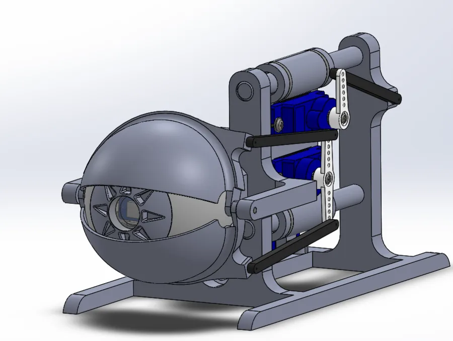
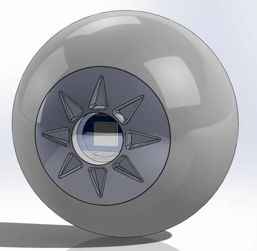
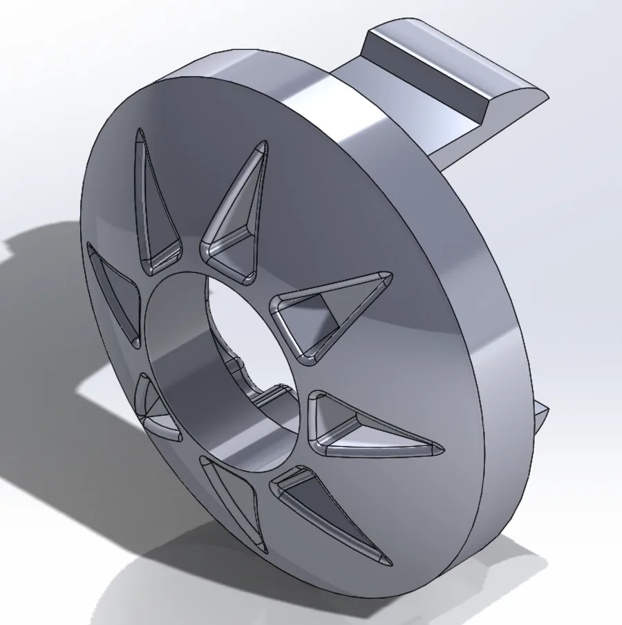
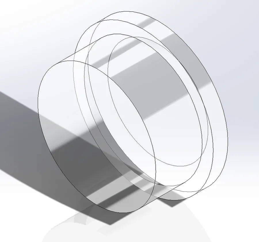
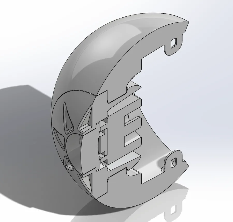
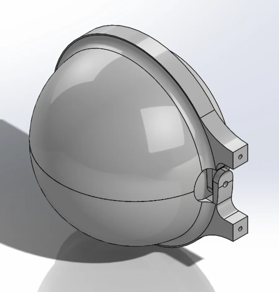
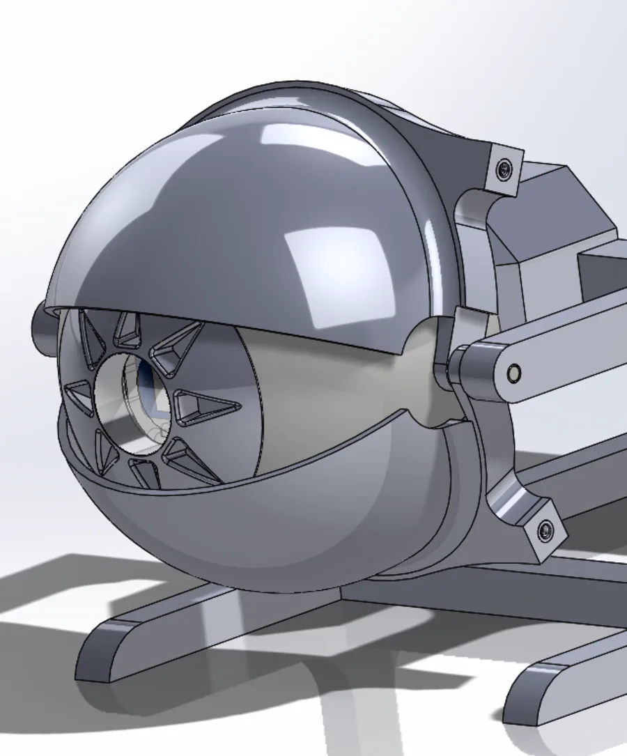
CAD RENDERS · THE EYEBALL ASSEMBLY IS THE PART THAT GOT PRINTED
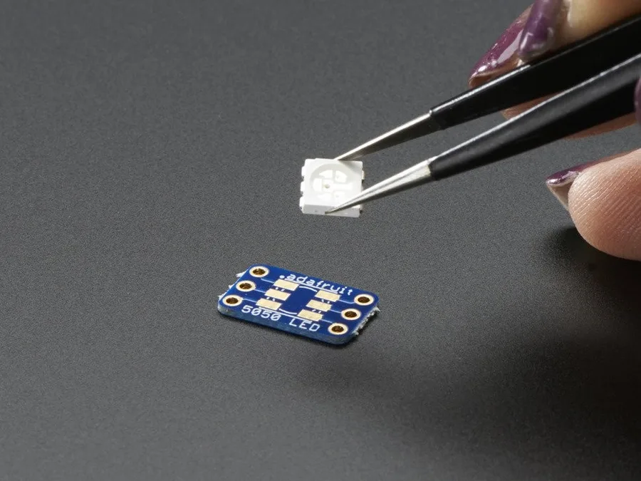
The whole mechanism is modeled in SolidWorks, but the eyeball assembly is the only part I printed before the budget ran out. No servos, no linkages, no working rig yet.
I'm keeping it here because I still like the design, especially the eyelid carriage. When I have spare money for parts I'll build the rest.
▸ NEXT · PRINT THE REST AND BUY THE SERVOS